Yet another metal hotend

Image

2013-05-20 21.08.19

I mention in my previous post one of the few things I’d so far been unable to fabricate for the child printer has been extruder gears. Yes, attempting current generation extruder gears with a 0.8 mm nozzle diameter results in nothing short of a blobby mess. It was clear that a self reproducing filament deposition machine could not easily exist in a scavenging society unless its nozzle was of sufficient resolution to print its own gears. This placed the nozzle squarely in the place of a bottleneck. While I had previously tested the first iteration of my hot end with 0.6 mm diameter, this solution was found to clog soon after anything of legitimate size was printed. As a result, I would conclude the nozzle needed to be reworked, from scratch.

This was not the only reason to rework the nozzle, however. The nozzle as it then stood was finicky between prints, and required long bouts of troubleshooting where the toaster wire was repeatedly removed and reinstalled to access the rest of the nozzle. This no doubt placed stress on the insulation used to guard the toaster wire from short circuits. Once, after a long session of troubleshooting I restarted the printer to find the toaster wire I’d used as a heating element start to short out, glowing red hot before briefly combusting the kapton tape, then overloading the PSU’s fuse and effectively shutting itself down. The event lasted no more than a second or so and was over before I’d reached for the off switch. With the heating element toast, it was pretty clear a new nozzle was needed.

Before continuing, let me say: I know full well that pre-fabricated hot ends are readily available off the internet for the right price. Still, I remain a dogged post-apocalyptic cheap skate. Nothing on the market at present is completely outside the reach of the common man, at least in function, and at the very least the machines used to make the hot ends can themselves be machined. Concessions are necessarily to ensure failsafe operation, but overall these concessions could still be limited to purchased components which could still in theory be procured from scavenging old parts, e.g. heating elements.

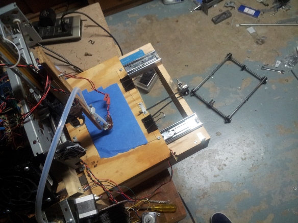
With that in mind, I’ll start off by outlining the needs I considered in designing the new nozzle. First, it was clear a heat resistor would be used in place of toaster wire. A heat resistor is inherently immune to short outs and would always provide a reliable resistance and wattage density, making it far safer than any toaster wire ever could be. A heat resistor, however, is a bulky thing, and using one would require a custom made heat block to hold it. Barring this, it could be that the entire nozzle would have to be custom made. Still, having only a drill press in my carpenter’s work shop I wanted to make sure these components could be fabricated without the help of a lathe.

Secondarily, I ideally wanted an all metal design which could enable printouts from material with higher melting points such as ABS and polycarbonate. This is a demanding task, though, and if need be I was willing to suffice with a metal hot end bearing a thin teflon lining to lubricate the filament through the isolator, much like the successful J-head nozzle. Doing this would at least remove the need for ordering thick rods of PEEK or Teflon from the internet. In either event, an nozzle made almost entirely from metal would require some sort of heat sink to act as a thermal break, possibly even requiring a fan.

There were still a dizzying number of diy hot ends on the reprap wiki which could fulfill these objectives, however none did quite exactly what I needed. Many, I found, required drilling long, straight holes through solid stainless steel threaded rod or carriage bolts in order to make a steel isolator. The kettle hat nozzle is a good example of a nozzle I tried like this. I tried a few good days trying to get holes such as this. Some limited success was had, but in the end none of the holes I drilled got anywhere near the length needed to support an isolator, heating block, and acorn nut nozzle tip. Even if I were successful in drilling a hole this length, I was very uncertain the process could be repeated for other diy-ers with their own drill press and work shop.

That was when I started to rethink these designs. Previously, I was working off the assumption the nozzle tip would be the most difficult component to machine since it required drilling through a block just far enough to the other side that you could drill the remaining way with a flimsy bit less than a millimeter in diameter. If the remaining wall was too thick, the small drill bit would likely break before any progress was made. In my previous nozzle design this led me to create my nozzle as is frequently done from an acorn nut.

Nevertheless, after very little effort I was able to drill my own custom made nozzle tips from blocks of aluminum. Going this route also allowed me to couple the heater block with the nozzle, saving space as well as reducing a extra joint at which leaks could occur. At the same time, I was finding it much harder to drill long distances through threaded rod in order to make the isolator. Given these findings, I refocused my design to make the isolator as easy to fabricate as possible. On a chance visit to hobby lobby, I found a good collection of metal tubing which could act as a pre-fabricated isolator:

2013-05-11 17.06.25

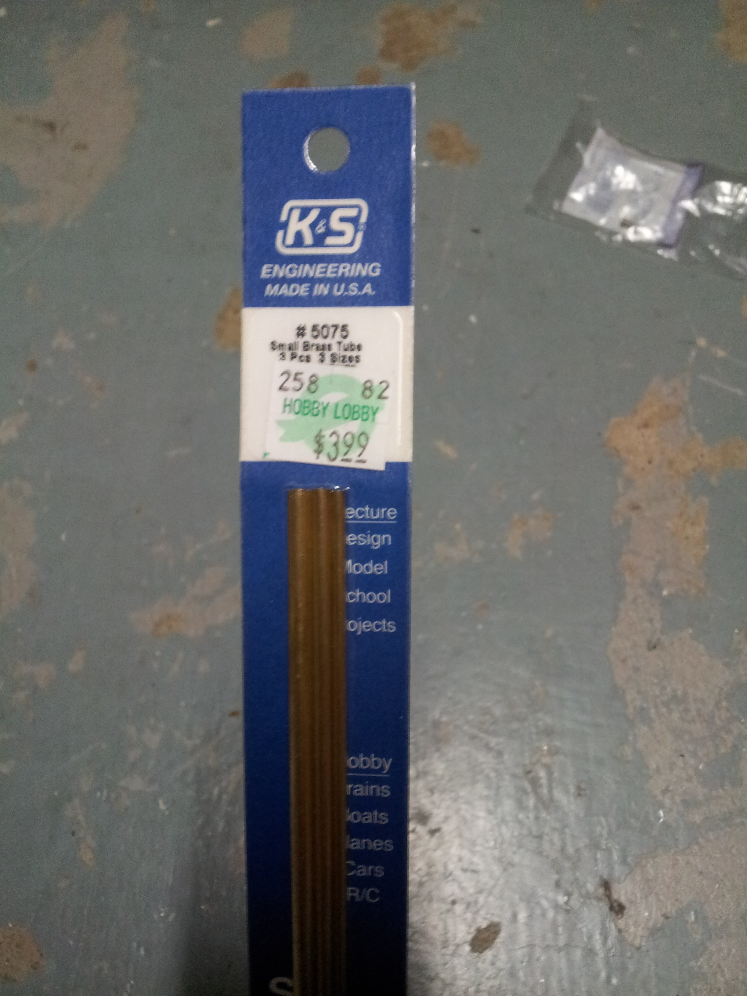
Tubing was available for many diameters in aluminum, copper, and brass. The 2mm diameter tubing fit perfectly with the teflon lining I’d already purchased for my previous nozzle iteration. I also chose the brass tubing given it has the lowest thermal conductivity of my three options. If any are hoping to replicate this nozzle, steel would be an even better choice assuming its available in your area.

A second heat block/nozzle tip was crafted that resembled the ones I’d tried with threaded rod, however this time around I drilled a hole that matched the diameter of the tubing I’d gotten from hobby lobby. The fit was intentionally made snug enough such that I had to bash the brass tubing into the heat block/nozzle tip with a rubber mallet (careful not to use a regular hammer – I’m quite certain it would bend the tubing!).

The heat sink I attached to the nozzle was originally meant to cool a series of mosfets in a computer I’d taken apart. It serindipitously fit snugly with the 2mm isolator I went with, however just in case it should come loose I tightened it further in place with a screw whose diameter roughly matched the distance between the rills in the heatsink. The contraption holds very steady without requiring any holes to be drilled in the heatsink.

2013-05-20 21.08.19

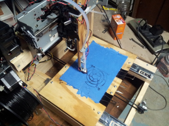
I tested the contraption on a printout of a star trek commbadge (shown here). At a few points when calibrating z-axis offset, I set the nozzle too low and crashed it into the bed. I was worried in this event the metal tubing would be flexible enough to bend out of shape, however after a few times of this occurring I believe its safe to say this does not occur.

A bigger issue occurred as I scaled up print size – the heat sink would saturate with heat and cause the filament to melt too early, in turn jamming the nozzle. I had anticipated this problem, however, and it was quickly resolved by screwing a scavenged pc fan to the heatsink.

2013-05-25 00.41.09

Now the heatsink is just a few degrees above room temperature, and the only limit to size now is the build space!

2013-06-01 03.22.33

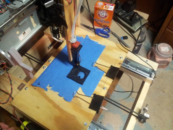
Shown below is the printer fabricating the chuck to a printable lathe, which will hopefully go on to further simplify hot end creation. In time, I hope to write up an article on the reprap wiki to document the design, with plenty of pictures to document the process. Switching out the drilled out threaded rods can definitely simply the construction of metal hot ends in the future.

What rough beast…

Image

What rough beast...

Work on the child printer (pictured above) begins in earnest. At the time the picture was taken only its y-axis drive train and base had been constructed. Nevertheless, with the benefit of an existing 3d printer, it becomes immediately obvious to me that construction of the child printer is far easier than its parent’s construction ever was. Overall, the greatest improvement has simply been the removal of mental overhead presented by the untested design of the parent printer. Questions I found myself constantly returning to on the parent printer (e.g. structural integrity, motor torque) are virtually eliminated now that there is the benefit of a design that has already been tested. Pre-designed printouts remove the need to think about the design and construction of a part to accomplish specific purposes. Printouts, while still crude when coming from the 0.8 mm nozzle, are still sturdy and capable of accomplishing their purposes. So far, I’ve found only the gears of the extruder are beyond the reach of the parent printer at this point, but plans are in the works to craft a better nozzle from scavenged parts that is capable of printing at the resolution needed for these finer pieces.

The child printer takes its design from the Prusa i3. The design is much less rigorously tested in comparison to the venerable Prusa Mendels before it, however uncertainty in design is not something I’m unfamiliar with. 🙂 More importantly, the Prusa i3 strips the number of printed parts to a minimum and shifts a significant portion of the frame to a wood or steel based construction. These two features make the Prusa i3 a no brainer given my current setup. Reducing the number of printed parts reduces the demand placed on an as-of-yet untested 3d printer, and a partial wood construction leverages the existing capability of my modest carpenter’s workshop.

Hot end, version 2

Image

Hot end, version 2

From the start of the project, it was pretty apparent the scavenged z axis was not designed for vertical motion and would easily fall under the weight of is own extruder. A bowden cable was the ready made solution, and rather than investigating the potential for polyethylene tubing I opted for the standard teflon setup. Most likely this would not be used in a scavenger society, yes. It turned out the teflon tubing I ordered was much larger in diameter than those found in most printers, but as I discovered it never made much a difference. Whats more, friction with a tube this large has never yet been a problem. This finding gives me hope for the potential in the more common polyethylene tubing you can find in any hardware store, though it may be a while before I care to give it a shot.

But that’s an aside. Problems at this point were becoming apparent with the bakelite isolator and a replacement was needed. Since I was already putting the bowden cable to use, I figured I might use it to my advantage. My idea was to incorporate the bowden cable into the nozzle itself. The teflon tubing was not only self lubricating, but was also well suited to high temperature applications. The diameter of my setup would not be able to guide the filament much, but a second tube of teflon I had used for nozzle lining would work to that end.

With no need for an isolator, I would then only need the heat block and nozzle. Brass acorn nuts are already frequently used for the nozzle and would be available in any hardware store, so as far as I was concerned that part was taken care of. This would mean the only problem really was in affixing the acorn nut to the isolator using only common, ready made parts. A 1/8″ pipe fitting was well suited for that, and as I found it fit okay against a 5/16″ acorn nut. As with the previous hot end, a 1/32″ or ~0.8mm hole was drilled through the acorn nut. This was chosen as it was the smallest drill bit I could find in local hardware stores, and I imagine any smaller drill bit would likely get lost or broken in the event society wasn’t around to make new ones.

Shown here is the resulting hot end, at work printing a fan cover for the one I had scavenged from an old computer.

Last leg of the old hot end

Image

Last leg of the old hot end

One of the first things printed to an immediate end turned out to be a z axis mount for a prusa i1 – not that I meant to make one of them, but it seemed apparent at the time the quickest way to improve print quality could be the z axis, which was (and still is) cobbled together from an old printer and not designed for vertical motion. As the print progressed though it became apparent there were larger issues at stake – the hot end leaked, bridging was unreliable, and accuracy was questionable even considering the thick 0.8mm nozzle I used. This would be the last print in which I’d work with this hot end.

And combining them into instruments yet stranger…

Image

And combining them into instruments yet stranger...

The electronics for the printer are not extraordinary – a set of 4 pololu stepper drivers wired to an arduino microcontroller. Originally, both the endstops and the arduino shields were wired by veroboard, however I found the standard veroboard configurations offered by the reprap wiki to be rather physically weak and ill fit for experimentation. After a while I switched over to breadboard, but that’s not to say I won’t return to pcb after getting the printer to print some circuitry.

Always buying strange instruments of glass and metal…

Image

Always buying strange instruments of glass and metal...

Despite all the talk of scavenging for parts, there were a few components I decided to get anyways. A lot of this was ordered before figuring out just what sort of theme I wanted from this project. All but one motor wound up not being used (the purpose of the one used motor will soon become clear). An extruder, while entirely possible to carve from scratch, would have been far too much effort put in just to make a point. The arduino and stepper drivers were very much still required.

Printer skeleton

Image

Printer skeleton

To be perfectly honest, at the time I actually had it in mind to go with a pure wolfstrap solution, however rather than waiting on some order for optoswitches I figured I’d go down to the thrift store and get some myself. Having stepper motors and structure come with the printers, it rapidly became clear that scavenging would outline the shape of things to come.

Shown here is the moving structure that came with the first printer. Unlike most parts I see online, the gears are solid metal and are of a much smaller diameter, thereby allowing smaller step size and in turn greater precision. The belts are ready made for these gears and are clearly capable of handling linear motion, which itself has driven the recent trend towards gt2 belts in the reprap community.

Optoswitches

Image

This model had 3 optoswitches, in total, however, this was not the only one I would have to take apart, and as I soon discovered the number can vary widely. The second printer I dissected contained only one. I should note I’m not the first one to try scavenging for optoswitches, nor did I come up with the idea independently.

A small, hapless printer

Image

A small, hapless printer

A printer was purchased at the salvation army for around $7. I made sure this one had a stepper motor to it – most modern printers work off cheaper servo motors. Nevertheless, there are still a few relatively recent printers I saw using steppers.

Oftentimes it seems the servos in printers today are little more than cheap DC motors with encoders strapped on. The encoders themselves appear just to be optoswitches reading patterns off flimy transparent film. The transparent film rotates around with the motor shaft and periodically spaced dark patches cover up the optoswitch, thus registering a “step”. This makes me think a similar process could be adapted to produce more affordable printers – dc motors would be cheaper and easier to find than steppers, and you could completely bypass the need for costly stepper drivers. Still, this would be more a firmware project than anything, since existing firmware to my knowledge rides on the assumption there is one pin to encode a step and another for direction. You would also loose the automatic breaking stepper motors have when not activated. This might have to require an entirely separate project unto itself…